High Temperature Load Cells Connection Methods
The high-temperature-resistance weighing is a specialized weighing technology widely used among metallurgy enterprises. The high-temperature-resistance steel-clad electronic scale adopted the multi-load cell modularized structure. For example, the steel-clad scale ranging from 1t to 300t adopts four 150t load cells, and the steel-clad scale ranging from 1t to 150t adopts four load cells. Products of the kind are characterized by high-temperature-resistance (the system could work steadily for a long time when the temperature is ≥250℃) and high-resistance (300% shock resistance).
Reasonable applications of the multi-load cell technology can create favorable working conditions for electronic weighing instruments, change the input and output characteristics, reduce the electronic weighing instruments' energy consumption, and improve the system's anti-interference ability. Therefore, to study the multi-load cell technology is of vital practical signifance.
1. Method for combination of high temperature load cells
The electronic weighing system adopts multiple load cells, and the commonly-adopted combination methods include the working mode in series, fully-parallel-connection working mode and working mode combining series connection and parallel connection.
1.1 Series connection work method
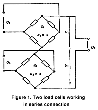
In the series connection, multiple load cells adopt the independent power supply for the bridge, and the output terminal adopts the series connection. See figure 1 below:

Assume that their bridge arm resistance is R1 and R2, respectively; their sensitivity is S1 and S2; their bridge voltage is U1 and U2; their full range is F. In order to ensure the normal series connection work mode, the following equation should be satiated: S1U1= S2U2.
Similarly, it can be proved that, when n load cells work in series, S1U1= S2U2=...=SnUn should be satisfied so as to ensure proper functioning. This is a basic condition for work in series connection. From the equation, it can be seen that the load cells in series connection can build the normal working status through regulation of the bridge voltage no matter how parameters of various load cells are. Of course, the dispersion of different parameters in practical applications should not be too large.
Series connection of load cells has the following characteristics:
1. Assume that there is one load, W. Use a load cell with the full range as F, sensitivity as S and bridge voltage as U for measurement. Obtain the output as U1= (SU/F) W. If two load cells work in series connection to measure the same load above, and under the ideal condition that eccentric load is not taken into consideration, the load cell with the full range as (1/2) F should be adopted. Assume that the sensitivity of the two load cells is S and the bridge voltage is U. Then, the total output is Un=2U1.
2. When the bridge arm resistance of two load cells is R, the output resistance after series connection is:
Rn=R+R=2R
Similarly, when n load cells work in series connection, then:
Un=nU1
Rn=nR
The Un and Rn above are the output signal and output resistance of n load cells after series connection. These two equations suggest that, when there are n load cells working in series connection, the n-fold output can be obtained compared with using one load cell. At the same time, the output resistance is n-fold as large as that of one load cell.
Under these conditions, particularly when the weight displayer's resolution rate is lower, more precise weighing results can be obtained. The defect is that, after series connection and under the situation of DC power supply, every load cell requires mutually independent bridge voltage power source. Otherwise, the original relationship of bridge circuits might be damaged, and the equipment complex and cost will be both increased. Upon AC power supply, the secondary winding of the power transformer should be completely the same to electronic scales requiring a high weighing accuracy. It is relatively difficult compared with the practical making process. Besides, after series connection, the output resistance of the load cell will be increased, which can easily cause interference. However, this method has been seldom adopted or almost eliminated.
1.2 Parallel connection work mode
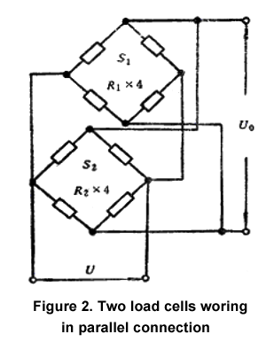
This work mode features parallel connection of the input terminal of various load cells. One public power bridge is used, and the output works in parallel connection. The parallel connection work mode of two load cells is shown in figure 2 below:

Assume that their bridge arm resistance is R1 and R2, respectively. Their sensitivity is S1 and S2; their bridge voltage is U1 and U2. Their full range is F. In order to ensure the normal series connection work mode, the following equation should be satiated: S1U1= S2U2. Obviously, parallel connection work mode has a high requirement of load cell's parameters.
Similarly, when there are n load cells working in parallel connection: S1/R1=S2/R2=...=Sn/Rn.
Characteristics of parallel connection work mode of two load cells are as below:
1. Assume that there is one load, W. Use a load cell with the full range as F, sensitivity as S and bridge voltage as U for measurement. Obtain the output as U1=WSU/F.
If two load cells work in series connection to measure the same load, w, and under the ideal condition that eccentric load is not taken into consideration, the load cell with the full range as (1/2) F should be adopted. Assume that the sensitivity of the two load cells is S and the bridge voltage is U. Then, the total output is Un=U1.
2. Assume that the bridge resistance of two load cells is both R, and the output resistance after parallel connection is Rn. Obvious, Rn=R/2 can be obtained.
Similarly, when there are n load cells working in full parallel connection, then:
Un=U1
Rn=R/n
In the above equation, Un=U1. Rn means the output signal and output resistance of n load cells working in parallel connection. These two equations suggest that, no matter how many load cells work in parallel connection, an output which is larger than that of an equivalent load cell cannot be obtained. However, the output resistance after parallel connection can be reduced to 1/n of a load cell.
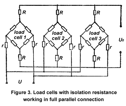
Under the condition that the weight displayer has a higher sensitivity or resolution ratio, parallel connection is a better choice, for it requires only one bridge power source, and the system is simple and economic. Moreover, we can use regulator circuit for the load cells to reduce the eccentric error. However, it requires the average deviation of every load cell's output resistance to be small and the load cell coefficient tolerance cannot be too large. Otherwise, when the load-bearing of several load cells is uneven, the average of the output voltage will generate errors. Under the condition of parallel connection, two isolated resistors are connected between two output terminals of every load cell and the weight displayer. Since the internal resistance of the load cell is the function of the output signal, the isolation resistance in series connection can reduce the influence of resistance changes on output. The total resistance of two isolation resistors of every load cell should be equal to each other, and the two resistance should be equal to each other as well. The tolerance should be small. All this is targeted at reducing the influence of unequal output resistance of load cells or inconformity of load cell coefficients on the load cell's total output. The wiring method is shown in figure 3.

As shown in figure 3, R is the isolation resistance and can be set to be around 10kΩ and its tolerance can be set to be 0.01%. The experimental results suggest that, when the loading of load cells working in parallel connection is uneven, the average error of load cells is smaller than 0.05%.
1.3 Series connection and parallel connection mixed work mode
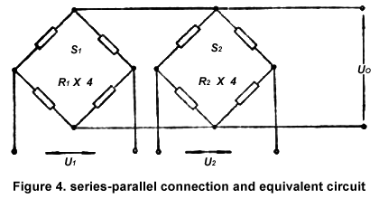
In this section, the series-parallel work mode mixing the above two work modes is discussed. Usually, every load cell uses the independent bridge power source, but the output adopts the parallel connection. See figure 4. This work mode is also known as the series and parallel connection mode.

After thorough analysis, the condition for two load cells working in series and parallel connection can be written as below:
S1U1/R1=S2U2/R2.
Therefore, the series and parallel connection work mode combines the advantages of the series connection work mode and the parallel connection work mode. No matter how the parameters of every load cell are, the bridge voltage can be adjusted to build a normal work status. Of course, the dispersion of load cell parameters cannot be too large.
Similarly, it can be proved that the output signal of n load cells working in series and parallel connection can be written as Un=Ui, and its total output resistance is Rn=R/n. As to four load cells of one electronic scale, though it is also ok to connect load cells in series two by two and then connect them in parallel or connect load cells in parallel two by two and then connect them in series, these two connection methods are not common to see in practical applications.
2. Comparison of three work modes
Through the above analysis of the three connection methods of the load cells, we clearly see that the number of bridge power supplies in the full parallel connection is the least, the energy saving effect is good, the anti-interference ability is the strongest, but the output signal is small. The serial connection has the largest output signal, but the anti-interference ability is the worst, and the energy-saving effect is not good. The series-parallel connection has the advantages and disadvantages of the previous two connection mode to varying degrees. In the multi load cells weighing system, what kind of connection mode should be selected, it should be considered and rationally selected according to the actual situation.
Reasonable applications of the multi-load cell technology can create favorable working conditions for electronic weighing instruments, change the input and output characteristics, reduce the electronic weighing instruments' energy consumption, and improve the system's anti-interference ability. Therefore, to study the multi-load cell technology is of vital practical signifance.
1. Method for combination of high temperature load cells
The electronic weighing system adopts multiple load cells, and the commonly-adopted combination methods include the working mode in series, fully-parallel-connection working mode and working mode combining series connection and parallel connection.
1.1 Series connection work method
In the series connection, multiple load cells adopt the independent power supply for the bridge, and the output terminal adopts the series connection. See figure 1 below:

Assume that their bridge arm resistance is R1 and R2, respectively; their sensitivity is S1 and S2; their bridge voltage is U1 and U2; their full range is F. In order to ensure the normal series connection work mode, the following equation should be satiated: S1U1= S2U2.
Similarly, it can be proved that, when n load cells work in series, S1U1= S2U2=...=SnUn should be satisfied so as to ensure proper functioning. This is a basic condition for work in series connection. From the equation, it can be seen that the load cells in series connection can build the normal working status through regulation of the bridge voltage no matter how parameters of various load cells are. Of course, the dispersion of different parameters in practical applications should not be too large.
Series connection of load cells has the following characteristics:
1. Assume that there is one load, W. Use a load cell with the full range as F, sensitivity as S and bridge voltage as U for measurement. Obtain the output as U1= (SU/F) W. If two load cells work in series connection to measure the same load above, and under the ideal condition that eccentric load is not taken into consideration, the load cell with the full range as (1/2) F should be adopted. Assume that the sensitivity of the two load cells is S and the bridge voltage is U. Then, the total output is Un=2U1.
2. When the bridge arm resistance of two load cells is R, the output resistance after series connection is:
Rn=R+R=2R
Similarly, when n load cells work in series connection, then:
Un=nU1
Rn=nR
The Un and Rn above are the output signal and output resistance of n load cells after series connection. These two equations suggest that, when there are n load cells working in series connection, the n-fold output can be obtained compared with using one load cell. At the same time, the output resistance is n-fold as large as that of one load cell.
Under these conditions, particularly when the weight displayer's resolution rate is lower, more precise weighing results can be obtained. The defect is that, after series connection and under the situation of DC power supply, every load cell requires mutually independent bridge voltage power source. Otherwise, the original relationship of bridge circuits might be damaged, and the equipment complex and cost will be both increased. Upon AC power supply, the secondary winding of the power transformer should be completely the same to electronic scales requiring a high weighing accuracy. It is relatively difficult compared with the practical making process. Besides, after series connection, the output resistance of the load cell will be increased, which can easily cause interference. However, this method has been seldom adopted or almost eliminated.
1.2 Parallel connection work mode
This work mode features parallel connection of the input terminal of various load cells. One public power bridge is used, and the output works in parallel connection. The parallel connection work mode of two load cells is shown in figure 2 below:

Assume that their bridge arm resistance is R1 and R2, respectively. Their sensitivity is S1 and S2; their bridge voltage is U1 and U2. Their full range is F. In order to ensure the normal series connection work mode, the following equation should be satiated: S1U1= S2U2. Obviously, parallel connection work mode has a high requirement of load cell's parameters.
Similarly, when there are n load cells working in parallel connection: S1/R1=S2/R2=...=Sn/Rn.
Characteristics of parallel connection work mode of two load cells are as below:
1. Assume that there is one load, W. Use a load cell with the full range as F, sensitivity as S and bridge voltage as U for measurement. Obtain the output as U1=WSU/F.
If two load cells work in series connection to measure the same load, w, and under the ideal condition that eccentric load is not taken into consideration, the load cell with the full range as (1/2) F should be adopted. Assume that the sensitivity of the two load cells is S and the bridge voltage is U. Then, the total output is Un=U1.
2. Assume that the bridge resistance of two load cells is both R, and the output resistance after parallel connection is Rn. Obvious, Rn=R/2 can be obtained.
Similarly, when there are n load cells working in full parallel connection, then:
Un=U1
Rn=R/n
In the above equation, Un=U1. Rn means the output signal and output resistance of n load cells working in parallel connection. These two equations suggest that, no matter how many load cells work in parallel connection, an output which is larger than that of an equivalent load cell cannot be obtained. However, the output resistance after parallel connection can be reduced to 1/n of a load cell.
Under the condition that the weight displayer has a higher sensitivity or resolution ratio, parallel connection is a better choice, for it requires only one bridge power source, and the system is simple and economic. Moreover, we can use regulator circuit for the load cells to reduce the eccentric error. However, it requires the average deviation of every load cell's output resistance to be small and the load cell coefficient tolerance cannot be too large. Otherwise, when the load-bearing of several load cells is uneven, the average of the output voltage will generate errors. Under the condition of parallel connection, two isolated resistors are connected between two output terminals of every load cell and the weight displayer. Since the internal resistance of the load cell is the function of the output signal, the isolation resistance in series connection can reduce the influence of resistance changes on output. The total resistance of two isolation resistors of every load cell should be equal to each other, and the two resistance should be equal to each other as well. The tolerance should be small. All this is targeted at reducing the influence of unequal output resistance of load cells or inconformity of load cell coefficients on the load cell's total output. The wiring method is shown in figure 3.

As shown in figure 3, R is the isolation resistance and can be set to be around 10kΩ and its tolerance can be set to be 0.01%. The experimental results suggest that, when the loading of load cells working in parallel connection is uneven, the average error of load cells is smaller than 0.05%.
1.3 Series connection and parallel connection mixed work mode
In this section, the series-parallel work mode mixing the above two work modes is discussed. Usually, every load cell uses the independent bridge power source, but the output adopts the parallel connection. See figure 4. This work mode is also known as the series and parallel connection mode.

After thorough analysis, the condition for two load cells working in series and parallel connection can be written as below:
S1U1/R1=S2U2/R2.
Therefore, the series and parallel connection work mode combines the advantages of the series connection work mode and the parallel connection work mode. No matter how the parameters of every load cell are, the bridge voltage can be adjusted to build a normal work status. Of course, the dispersion of load cell parameters cannot be too large.
Similarly, it can be proved that the output signal of n load cells working in series and parallel connection can be written as Un=Ui, and its total output resistance is Rn=R/n. As to four load cells of one electronic scale, though it is also ok to connect load cells in series two by two and then connect them in parallel or connect load cells in parallel two by two and then connect them in series, these two connection methods are not common to see in practical applications.
2. Comparison of three work modes
Through the above analysis of the three connection methods of the load cells, we clearly see that the number of bridge power supplies in the full parallel connection is the least, the energy saving effect is good, the anti-interference ability is the strongest, but the output signal is small. The serial connection has the largest output signal, but the anti-interference ability is the worst, and the energy-saving effect is not good. The series-parallel connection has the advantages and disadvantages of the previous two connection mode to varying degrees. In the multi load cells weighing system, what kind of connection mode should be selected, it should be considered and rationally selected according to the actual situation.

