
Tension Load Cell Application at Container Eccentric Load Calibration
Discussion on the eccentric load calibration method of eccentric load detection device for suspended container.
1. The relevant regulations for container weighing and the working principle and technical characteristics of the eccentric load detection device of suspended containers
1.1 Relevant regulations for container weighing
1.1.1 Relevant regulations for railway freight department
According to the regulations of railway freight loading and reinforcement , after loading, the projection of goods total center of gravity should be located at the intersection of the vertical and horizontal central lines of the freight car floor. In case of a necessary deviation, the transverse deviation shall not exceed 100 mm. If it's larger than 100mm, counterweight measures should be taken. In case of a vertical deviation, each vehicle bogie shall not bear more than one-half of the allowable loads of the truck, and the difference of bearing weight between two bogies shall not be greater than 10 ton. Weight of goods (including the packages, protective objects, reinforcement materials and devices) loaded on truck shall not exceed the allowable load weight. According to the requirements of railway freight safety inspection, monitoring and management system: when the train is weighed at a speed of 40 km/h or below, total accuracy of weighing shall be ≤0.5%. The eccentric load (longitudinal overload measurement), also referring to the range of overload difference value between front and rear bogies, shall not be more than 400 kg when the train is weighed at a speed of 40 km/h or below. The absolute value of difference between the average eccentric load difference of front and back bogies and the theoretical weight difference shall not be more than 500 kg. The center of gravity deviation based on vehicle axes (transverse overload measurement) (the loading reinforcement shall be no more than 100 mm), the absolute value of difference between the average deviation rate and the theoretical deviation rate of deviated bogies shall be no more than 5%. The absolute value of average initial bias rate of 68 ton or 76 ton vehicles without a bias check and balance shall be no more than 5%.
1.1.2 Relevant regulations for maritime board
SOLAS Convention has regulated the safety of container maritime transport, namely shipper shall bear the responsibility of verifying the total weight of freight containers. The cargo owner shall ensure that the verified container weight is reflected on the transport documents, the error range between the verified weight provided by the shipper and the verified container weight obtained at the maritime authority, carrying vessel, carrier or wharf operator shall not exceed ±5% or 1 ton (selecting the smaller one).
1.2 Working principle and technical characteristics of the eccentric load detection device of suspended containers
1.2.1 Working Principle
The detection device is mainly composed of tension load cell, load cell amplifier, wireless signal transmitter, wireless signal receiver, CPU and HMI. The tension load cells are installed on four revolving locks of the container crane to test the force on four corners of container. The load cell amplifier converts the signal of tension load cells into standard analog signal which can be collected and processed, and then the wireless signal transmitter transmits this signal to the wireless signal receiver. CPU acquires the signal at the wireless signal receiver and gets the container weight and eccentric load value after data processing, then display the data on human-machine interface, record and print the data. In case of overload or eccentric load, the detection device sends out sound and light alarm reminder, and the operator shall make corresponding treatment in time, complete the storage and management of all detection data (including the lifting time, container number, total weight, eccentric load, operator number), so as to look up and print at anytime.

Device workflow principle: tension load cell - load cell amplifier - wireless signal transmitter- wireless signal receiver - CPU - HMI - printer. The system is shown in figure 1. The structure of the device is shown in figure 2.
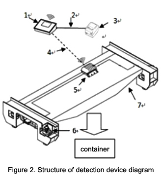
In figure 2, 1 - Load cell controller, 2 - RS232 communication cable, 3 - Printer, 4 - Wireless signal communication, 5 - A/D signal processor and wireless communication module, 6 - Load cell (mounted in 4 revolving locks positions), 7 - Container lifting devices.
1.2.2 Technical characteristics
A. The load cells of the device is installed in the revolving locks of portal (bridge) crane container lifting device upper bracket, and the load cell controller is installed in the cab of the portal (bridge) crane, which can monitor the container total weight and eccentric load of container cargo in the lifting process.
B. The weighing accuracy level of the detecting device should not be lower than Y(b) level, and the eccentric position of the container X-axis (length direction) and Y-axis (width direction) can be measured and output. It can be set to alarm when the X-axis (length direction) eccentricity exceeds the container length ±5%, and the eccentric position of the Y-axis (width direction) is greater than ±100 mm alarm.
C. The weight and eccentric signals are respectively transmitted to the load cell controller by wireless transmission and then send to railway carriage terminal (serial port).
D. Main technical parameters of the detection device
2.1 Eccentric load calibration
2.1.1 Set the position of eccentricity of center of gravity
The eccentricity of center of gravity, refers to the deviation value in axial and lateral direction between actual center of gravity and cross point of diagonal of the four corners, whether it is an empty container, a heavy container, or with/without attachments. And the unit of measurement is mm. The eccentric load calibration is using a 20 GP container. A rectangular coordinate system is established on the bottom plate. Three points O (0,0), A (600,100), B (-600,-100) are selected for loading and measuring the eccentric load. The position setting of eccentricity of center of gravity is shown in Figure 3.

2.1.2 Calibration process
2.1.3 Mechanical analysis of eccentric load measurement error
3. Application evaluation
1. The relevant regulations for container weighing and the working principle and technical characteristics of the eccentric load detection device of suspended containers
1.1 Relevant regulations for container weighing
1.1.1 Relevant regulations for railway freight department
According to the regulations of railway freight loading and reinforcement
, after loading, the projection of goods total center of gravity should be located at the intersection of the vertical and horizontal central lines of the freight car floor. In case of a necessary deviation, the transverse deviation shall not exceed 100 mm. If it's larger than 100mm, counterweight measures should be taken. In case of a vertical deviation, each vehicle bogie shall not bear more than one-half of the allowable loads of the truck, and the difference of bearing weight between two bogies shall not be greater than 10 ton. Weight of goods (including the packages, protective objects, reinforcement materials and devices) loaded on truck shall not exceed the allowable load weight. According to the requirements of railway freight safety inspection, monitoring and management system: when the train is weighed at a speed of 40 km/h or below, total accuracy of weighing shall be ≤0.5%. The eccentric load (longitudinal overload measurement), also referring to the range of overload difference value between front and rear bogies, shall not be more than 400 kg when the train is weighed at a speed of 40 km/h or below. The absolute value of difference between the average eccentric load difference of front and back bogies and the theoretical weight difference shall not be more than 500 kg. The center of gravity deviation based on vehicle axes (transverse overload measurement) (the loading reinforcement shall be no more than 100 mm), the absolute value of difference between the average deviation rate and the theoretical deviation rate of deviated bogies shall be no more than 5%. The absolute value of average initial bias rate of 68 ton or 76 ton vehicles without a bias check and balance shall be no more than 5%.1.1.2 Relevant regulations for maritime board
SOLAS Convention has regulated the safety of container maritime transport, namely shipper shall bear the responsibility of verifying the total weight of freight containers. The cargo owner shall ensure that the verified container weight is reflected on the transport documents, the error range between the verified weight provided by the shipper and the verified container weight obtained at the maritime authority, carrying vessel, carrier or wharf operator shall not exceed ±5% or 1 ton (selecting the smaller one).
1.2 Working principle and technical characteristics of the eccentric load detection device of suspended containers
1.2.1 Working Principle
The detection device is mainly composed of tension load cell, load cell amplifier, wireless signal transmitter, wireless signal receiver, CPU and HMI. The tension load cells are installed on four revolving locks of the container crane to test the force on four corners of container. The load cell amplifier converts the signal of tension load cells into standard analog signal which can be collected and processed, and then the wireless signal transmitter transmits this signal to the wireless signal receiver. CPU acquires the signal at the wireless signal receiver and gets the container weight and eccentric load value after data processing, then display the data on human-machine interface, record and print the data. In case of overload or eccentric load, the detection device sends out sound and light alarm reminder, and the operator shall make corresponding treatment in time, complete the storage and management of all detection data (including the lifting time, container number, total weight, eccentric load, operator number), so as to look up and print at anytime.
Device workflow principle: tension load cell - load cell amplifier - wireless signal transmitter- wireless signal receiver - CPU - HMI - printer. The system is shown in figure 1. The structure of the device is shown in figure 2.
In figure 2, 1 - Load cell controller, 2 - RS232 communication cable, 3 - Printer, 4 - Wireless signal communication, 5 - A/D signal processor and wireless communication module, 6 - Load cell (mounted in 4 revolving locks positions), 7 - Container lifting devices.
1.2.2 Technical characteristics
A. The load cells of the device is installed in the revolving locks of portal (bridge) crane container lifting device upper bracket, and the load cell controller is installed in the cab of the portal (bridge) crane, which can monitor the container total weight and eccentric load of container cargo in the lifting process.
B. The weighing accuracy level of the detecting device should not be lower than Y(b) level, and the eccentric position of the container X-axis (length direction) and Y-axis (width direction) can be measured and output. It can be set to alarm when the X-axis (length direction) eccentricity exceeds the container length ±5%, and the eccentric position of the Y-axis (width direction) is greater than ±100 mm alarm.
C. The weight and eccentric signals are respectively transmitted to the load cell controller by wireless transmission and then send to railway carriage terminal (serial port).
D. Main technical parameters of the detection device
- Maximum weighing (Max): 40 ton.
- The scale division value (e) is generally 50kg or 100kg. If other values are expressed, it should be expressed as 1×10k, 2×10k or 5×10k, where 'k' is a positive integer, a negative integer or zero.
- The relative error of the eccentric load of O point is not more than ±8%.
- When the eccentric position of the Y-axis (width direction) exceeds ±100 mm, detection device alarms.
- When the X-axis (length direction) is eccentrically more than ±5% of the length of the container, detection device alarms.
-
Temperature range: -20~+40℃
2.1 Eccentric load calibration
2.1.1 Set the position of eccentricity of center of gravity
The eccentricity of center of gravity, refers to the deviation value in axial and lateral direction between actual center of gravity and cross point of diagonal of the four corners, whether it is an empty container, a heavy container, or with/without attachments. And the unit of measurement is mm. The eccentric load calibration is using a 20 GP container. A rectangular coordinate system is established on the bottom plate. Three points O (0,0), A (600,100), B (-600,-100) are selected for loading and measuring the eccentric load. The position setting of eccentricity of center of gravity is shown in Figure 3.
2.1.2 Calibration process
2.1.3 Mechanical analysis of eccentric load measurement error
3. Application evaluation
- The railway department has traceability requirements for the eccentric load display controllers of container overload and eccentric load detection devices. It calibrates the eccentric load display controllers of container overload and eccentric load detection devices in the company according to the main methods mentioned in this article, and then measure to confirm the calibration results. Based on the calibration results, containers whose eccentric load conforms to the requirements could be loaded. After the detection and confirmation from railway freight car overload and eccentric load detecting device, over-tolerance of eccentric load data is effectively reduced.
-
The calibration method mentioned in this article is operated with 20 GP container, M12-grade nominal value 2 ton and 3 ton standard weights, standard weights center positioning base/forklift truck and other standard devices and supporting facilities. The standard devices and supporting facilities are common equipment. This measuring method is simple and easy to operate. Corresponding data are convenient for computer processing and statistics. Reference value of the calibration point coordinate is selected as the same with the limit error stipulated in railway freight loading and reinforcement, which can meet the needs of traceability of measurement value of railway special measuring instruments.